Showing posts with label differential pressure. Show all posts

Using Orifice Plates to Measure Flow

The orifice plate is the simplest of the flowpath restrictions used in flow detection, as well as the most economical. Orifice plates are flat plates 1/16 to 1/4 inch thick. They are normally mounted between a pair of flanges and are installed in a straight run of smooth pipe to avoid disturbance of flow patterns from fittings and valves.

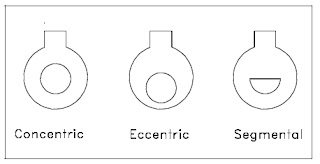
Three kinds of orifice plates are used: concentric, eccentric, and segmental (as shown in Figure 1).
orifice plate
Fig. 1 - Orifice plates (click for larger view)
The concentric orifice plate is the most common of the three types. As shown, the orifice is equidistant (concentric) to the inside diameter of the pipe. Flow through a sharp-edged orifice plate is characterized by a change in velocity. As the fluid passes through the orifice, the fluid converges, and the velocity of the fluid increases to a maximum value. At this point, the pressure is at a minimum value. As the fluid diverges to fill the entire pipe area, the velocity decreases back to the original value. The pressure increases to about 60% to 80% of the original input value. The pressure loss is irrecoverable; therefore, the output pressure will always be less than the input pressure. The pressures on both sides of the orifice are measured, resulting in a differential pressure which is proportional to the flow rate.
Orifice plate flow pattern
Orifice plate flow pattern (click for larger view)

Differential Pressure Transmitter
Differential pressure
transmitter used to
calculate flow.
(Yokogawa)
Segmental and eccentric orifice plates are functionally identical to the concentric orifice. The circular section of the segmental orifice is concentric with the pipe. The segmental portion of the orifice eliminates damming of foreign materials on the upstream side of the orifice when mounted in a horizontal pipe. Depending on the type of fluid, the segmental section is placed on either the top or bottom of the horizontal pipe to increase the accuracy of the measurement.

Eccentric orifice plates shift the edge of the orifice to the inside of the pipe wall. This design also prevents upstream damming and is used in the same way as the segmental orifice plate.

Orifice plates have two distinct disadvantages; they cause a high permanent pressure drop (outlet pressure will be 60% to 80% of inlet pressure), and they are subject to erosion, which will eventually cause inaccuracies in the measured differential pressure.

Contact Power Specialties with any process flow question or requirement. You can find them by visiting https://powerspecialties.com or by calling (816) 353-6550.

Understanding Differential Flow Elements

Differential Pressure Loop Diagram
(courtesy of Yokogawa)
The differential flow meter is the most common device for measuring fluid flow through pipes. Flow rates and pressure differential of fluids, such as gases vapors and liquids, are explored using the orifice plate flow meter in the video below.

The differential flow meter, whether Venturi tube, flow nozzle, or orifice plate style, is an in line instrument that is installed between two pipe flanges.

The orifice plate flow meter is comprised the circular metal disc with a specific hole diameter that reduces the fluid flow in the pipe. Pressure taps are added on each side at the orifice plate to measure the pressure differential.

According to the Laws of Conservation of Energy, the fluid entering the pipe must equal the mass leaving the pipe during the same period of time. The velocity of the fluid leaving the orifice is greater than the velocity of the fluid entering the orifice. Applying Bernoulli's principle, the increased fluid velocity results in a decrease in pressure.

As the fluid flow rate increases through the pipe, back pressure on the incoming side increases due to the restriction of flow created by the orifice plate.

The pressure of the fluid at the downstream side at the orifice plate is less than the incoming side due to the accelerated flow.

With a known differential pressure and velocity of the fluid, the volume metric flow rate can be determined. The flow rate “Q”, of a fluid through an orifice plate increases in proportion to the square root the pressure difference on each side multiplied by the K factor. For example if the differential pressure increases by 14 PSI with the K factor of one, the flow rate is increased by 3.74.

Showing the Difference in Function Between High and Low Pressure Ports on a Differential Pressure Transmitter

The following video demonstrates the different responses of a differential pressure transmitter to both positive and negative pressures applied to its high and low pressure ports. The response of pressure and vacuum to the "high" port is opposite the effect of pressure and vacuum (respectively) applied to the "low" port.

Yokogawa Pressure Handbook: A Basic Guide to Understanding Pressure

Pressure, temperature, level and flow are the four common plant measurements. Of the four, pressure is the most fundamental and common. The three remaining measurements can be inferred from pressure-flow (orifice plates, pitot tube, venturi), level (hydrostatic ‘Head’ pressure), and temperature (pressure thermometer). It can even be used to infer density (pressure for a given volume) and weight (load cells). If you cannot measure it, you cannot control it.

The ability to quickly, accurately, and reliably measure pressure is invaluable when trying to control a process.


Each of these types of transmitters measures pressure. The ow transmitter, liquid level transmitter, and pressure thermometer use the measured pressure to infer another process parameter.

Read the handbook below to garner a great understanding of industrial pressure measurement.

For more information on any industrial pressure requirement, visit http://www.powerspecialties.com or call (816) 353-6550.

Dynamic Compensation for Static Pressure Effects in Differential Pressure Measurement

Yokogawa DPharp
Yokogawa DPharp
Attaining the best available performance and accuracy from any measuring device utilized in an industrial process is always advantageous. The scale of most industrial processes is such that even small inaccuracies in process measurement produce financially tangible impact. Differential pressure measurement, with wide application in the industrial process sphere, can be improved with the addition of a means to compensate for the real world effects of static pressure upon instrument performance.

Yokogawa Corporation has developed a means to dynamically compensate for static pressure effects in field measurements. The brief technical presentation below will help you understand how static pressure effects can impact your field measurements, as well as how Yokogawa’s Real-time Dynamic Compensation works to offset its impact.

More detailed product and application information is available from your Yokogawa specialist.

Unique DP Cell Design Allows for Simultaneous Differential Pressure and Static Pressure Sensing

DPharp
Design eliminates additional
hardware requirements.
DPharp digital sensor has the unique ability to simultaneously measure static pressure and differential pressure. Additionally capsule and housing temperatures are also measured. Multi-sensing platform enables real-time dynamic compensation for unmatched precision and forms the basis for implementation of advanced diagnostics. These information are available through various digital communication protocols; providing additional insight into your process. Multi-sensing functionality with guaranteed accuracy of static pressure signal allows the process to operate with fewer devices delivering reduced lifecycle costs


For more information please read the document below: