Failure Prevention: Detecting Hot Spots in Air Cooled Generators

GCM-A
General Condition Monitor
(courtesy of E ONE Utility Systems)
Because of advancements in air-cooled generator designs and their increasingly higher power ratings, significantly greater stresses on materials and structures is increasing the probability of overheating. An early warning system for generator hotspots can mean the difference between a brief shut down for minor repairs versus a major and costly overhaul. The solution is to incorporate Generator Condition Monitors for Air Cooled Apparatus (GCM-A).

High concentrations of sub-micrometer particles (pyrolysis products) are released whenever any material is heated sufficiently to create thermal decomposition. The GCM-A detects the pyrolysis particles emitted into the cooling air (or ambient air) as a result of overheating or arcing.

The GCM-A monitors multiple air sample lines (locations) using a highly sensitive particle detector. The detector used to make these invisible particles large enough to monitor for concentration is a Wilson Cloud Chamber. The Wilson Cloud Chamber has been used and proven effective as an early warning, air sampling type, fire detector for several decades.

One sample line monitors ambient air, which serves as a reference since the particle level in the ambient air can change significantly and influence the particle level of the generator cooling air. One or more additional sample lines (or probes) are used to monitor the generator cooling air, which is compared against the particle level of the ambient air. High particle levels in the generator cooling air, without a corresponding increase in the ambient air, confirms the source of the pyrolysis particles is from within the generator. Conversely, if the particle level in the ambient air increases the source of the overheating must be outside the generator.

A more in-depth review detecting hot spots in air cooled generators can be found here.

To discuss your interest in this application, please contact:

Power Specialties, Inc.
9118 E. 72nd Terrace
Raytown, MO 64133
Toll Free: (800) 432-6550
Phone: (816) 353-6550
Fax: (816) 353-1740

Operating Principles, Applications, and Advantages of Coriolis Mass Flowmeters

coriolis effect
Image courtesy of
Wikipedia

Oscillation without flow
(courtesy of Wikipedia)
The Coriolis effect acts on a medium that is accelerated through a rotating system, like a ball on a rotating disk its movement is straight, however, if the observer turns with the disk the ball is apparently deflected.

The same effect occurs with a water hose that rotates around its own axis, like a skipping rope. As soon as water flows through the host also twists. The twisting is stronger or weaker, depending on the amount of water flowing through the hose.

Oscillation with flow
(courtesy of Wikipedia)
The Coriolis effect also appears with an oscillating movement, and in a Coriolis flowmeter, two symmetric metal tubes are set vibrating by an internal driver coil. The tubes oscillate with a resonance frequency similarly to that of a tuning fork.

The oscillation is measured precisely by two pick-ups at the inlet and outlet sections. If liquids or gases flow through the tubes, a phase shift occurs the pickups measure the spatial and temporal displacement (twist). The amount of twist is proportional to the mass flow rate of fluid passing through the tubes. The greater the amount, the stronger the tubes oscillate outwards.

Finally, sensors and transmitters are used to measure the twist and create a linear flow signal as an output for monitoring and control.

Coriolis mass flowmeters are widely used throughout the process measurement and control field. Their basic operating principle, combined with modern sensor and signal processing technology,
Rotamass by Yokogawa
Yokogawa ROTAMASS
Coriolis Flowmeter
provide a list of positive aspects.
  • Directly measure mass flow rate based on the principle of measurement.
  • Measure the mass flow rate with high accuracy of ±0.1%.
  • Provide a wide usable measurement range.
  • Deliver density measurement based on oscillating frequency.
  • Not materially impacted by fluid viscosity or density.
Coriolis flowmeters also do not need straight pipe sections upstream or downstream of the flowmeter. They also have the ability to measure non-conductive fluids.

The video below is produced by Yokogawa, a world class manufacturer of industrial process measurement and control instrumentation. It provides a clear and insightful illustration of the Coriolis principle and how it is used to provide accurate mass flow measurement.

Use High Visibility Dials on Pressure and Temperature Instruments

Reotemp HiVis Dials
Reotemp HiVis Dials
Here is a real-life case study of how high visibility (HiVis) dials on pressure and temperature gauges improved safety and efficiency at a US power plant.

Like most industrial plants, there were a number of recessed areas where light was blocked by equipment, piping, etc. This created low-light areas and shadows that can make it difficult to see and read instrumentation like pressure gauges. In some cases, gauges were mounted high above head and were difficult to read from the floor.

When gauges are hard to locate and read, it makes the operator’s job more difficult and increases the likelihood of human error.

Without Hi-Vis Dial
  • Gauges can be misread.
  • Gauges can be misidentified.
  • Gauges can be overlooked. 
With Hi-Vis Dial
  • Gauges are more easily seen in low light environments.
  • Gauges are easier to read at a distance.
  • Gauges are more noticeable and easier to locate.
  • Safety is increased. Hi-Vis = Hi-Safety.
After walking around the plant and evaluating the gauge’s visibility in a few low-light areas, the plant supervisor was confident the Hi-Vis dials would increase gauge visibility and plant safety. The decision was made to transition every gauge in the facility to the Hi-Vis dials.

In the following months, over 100 Hi-Vis dial pressure gauges were installed. The operators were now able to easily locate and read all of the pressure gauges. The plant’s supervisor had successfully increased the safety in his facility and has continued to use the Hi-Vis as the standard for all new pressure gauge applications. Plans are underway to replace all existing gauges in the Cooling Towers and Chiller Plant

For more information, contact:
Power Specialties, Inc.
9118 E. 72nd Terrace
Raytown, MO 64133
Toll Free: (800) 432-6550
Phone: (816) 353-6550
Fax: (816) 353-1740

Magnetic Level Gauges for Visual Tank Level Monitoring and Control

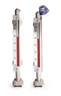
Magnetic Level Gauges
(courtesy of Hawk Measurement)
Magnetic Level Gauges (MLG) are widely applied in the monitoring and process control of liquid level and interface for many industries; such as petroleum, chemical, power, paper, metallurgy, water treatment etc. They are suitable for real time, precise, safe and reliable continuous measurement of process level.

Based on the principle of magnetic coupling and buoyancy, the magnetic level gauge provides real-time measurement for level and interface. The Magnetic Level Gauge (MLG) is connected to a process vessel. Within the chamber is a float containing a 360° magnetic ring. Outside of the chamber is an indicator equipped with a vacuum glass tube, which contains a bi-colored two-face magnetic bargraph. In response to the level movement, the float moves accordingly, forcing the magnetic bargraph to turn and change color. True liquid level is indicated or “read” from the corresponding point on the measuring scale. The indicator uses hermetical sealed glass tube technology to clearly indicate the level, which eliminates the common problems of glass gauges, such as vapor, condensation and liquid leakage etc.

Typical Applications:
  • Boiler: Steam drum liquid level
  • Power generation: Auxiliary machinery liquid level (HP reheater, LP reheater, deaerator, condenser and heating network heater etc), chemical water
  • Coal Chemical: Methanol, dimethyl ether, synthesis ammonia/urea, MTO, CTL, SNG
  • Silicon industry: Organic silicon, polycrystalline silicon
  • Petroleum and petrochemical: Oil and gas, ethylene, trimerization and etc.
  • Fine Chemicals: Methane oxide, epoxy ethane, aniline, PTMEG, BDO, carbon fiber, POM,acetic acid, styrene, rubber, crude benzol refining
  • Others: Metallurgy, paper-making, water treatment, biological, pharmaceutical, food and beverage etc.
Magnetic Level Gauges have a simple modular design, composed a main chamber, a float and an
mag level gauge construction
Mag level gauge construction
indicator.

Typical main chamber features:

  • ANSI standard design or special manufacture
  • Multi-forms installation and process connection
  • Chamber Material: 304/304LSS, 316/316LSS, 317SS, 321SS, 347SS, Ti2, Hastelloy C-276, Zr-702, Nickel-6, 304+PTFE, CPVC and PP.

Typical float features:

The float is the key component of the level gauge, which magnetically couples to the outside indicator, liquid level switch and transmitter.

  • Hermetically sealed incompressible
  • 360° magnetic ring
  • 316LSS, Hastelloy C-276, Zr-702, Nickel 6, Ti2, 304SS+PFA, grade V aviation titanium alloy and other materials
  • Special structure and precision manufacturing technology of pulse TIG and laser weld
  • Range of temperature: -320 to 1000°F (-196 to 538°C)
  • Range of pressure: vacuum to 600 psig (vacuum to 42MPa)
  • Suitable for harsh working conditions, such as HTHP, cryogenics and strong corrosion.
mag level float
Relationship of float, chamber and indicator.
Typical indicator features:
  • 316SS or aluminium ruler
  • Hermetically sealed glass tube with no contact with medium
  • Magnetic bargraph is made from special high and low temperature - resistant materials
  • Magnetic bargraph is mechanically interlocked to avoid random rotating
  • Selectable engineering units
  • Immune to oxidation, corrosion and the effects of dust