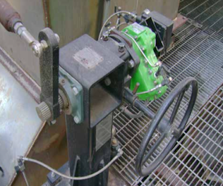
Maleic Anhydride Scrubbing Application

Ejector-Venturi Scrubber
S&K Ejector-Venturi Scrubber
Schutte & Koerting, a manufacturer of steam jet vacuum systems, steam jet heaters, exhausters and compressors, scrubber systems, desuperheaters, thermocompressors, eductors, ejectors, and valves, was asked to develop a special Ejector-Venturi Scrubber for a specialty chemical producer.

Background

Ejector Venturi Gas Scrubbers are very effective at removing noxious gases, particulates, odors, fumes and dusts from gas streams. Particulate contaminants are removed through impaction by the high velocity spray of scrubbing liquid. Gases and odors are eliminated through absorption and/or chemical reaction between the gases and scrubbing liquid. When properly matched to the application, these scrubbers, by their nature, are better able to cope with the high temperatures, heavy contaminant loads, and corrosive conditions often encountered.

Maleic Anhydride Scrubbing Challenges

Processes for making one of the raw materials (maleic anhydride) used in resin production generates contaminated off-gases. Maleic Anhydride is absorbed fairly readily in water producing Maleic Acid. However, maleic anhydride transforms directly from gaseous to solid state when cooled and, as a result, can easily plate out on scrubber internal surfaces building up and causing plugging. In order to minimize this “maintenance headache” a special ejector- venturi design is utilized.

Custom Ejector-Venturi Scrubber
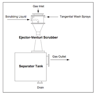
The gas inlet and liquid inlet orientations are reversed such that the gas inlet is from the top and the liquid inlet from the side. This allows for the installation of tangential wash sprays just below the gas inlet to wash the walls and keep them wetted. As a result the dry/wet interface is eliminated in the body section where most plugging typically occurs.

Other applications utilizing same special design:
  • Removal of chlorinated silanes, which tend to form “sticky” gels during scrubbing
  • Removal of elemental sulfur from sulfur holding tank vent exhausts 
Results:  At 50 – 10,000 ACFM gas rates, 90+% removal efficiency ejector-venturi per stage.

For more information on steam jet vacuum systems, steam jet heaters, exhausters and compressors, scrubber systems, desuperheaters, thermocompressors, eductors, or ejectors, contact:

Power Specialties, Inc.
9118 E. 72nd Terrace
Raytown, MO 64133
Toll Free: (800) 432-6550
Phone: (816) 353-6550
Fax: (816) 353-1740

The 2 Most Common Industrial Temperature Sensors

industrial temperature sensors
Thermocouple & RTDs come in many shapes,
styles, and configurations.
This blog post will introduce the reader to the two most common industrial temperature sensors - the thermocouple and RTD (resistance temperature detector).

A thermocouple is a temperature sensor that produces a micro-voltage from a phenomena called the Seebeck Effect. In simple terms, when the junction of two different (dissimilar) metals varies in temperature from a second junction (called the reference junction), a voltage is produced. When the reference junction temperature is known and maintained, the voltage produced by the sensing junction can be measured and directly applied to the change in the sensing junctions' temperature.

Type K thermocouple
Diagram of Type K thermocouple circuit
Thermocouples are widely used for industrial and commercial temperate control because they are inexpensive, sufficiently accurate for many uses, have a nearly linear temperature-to-signal output curve, come in many “types” (different metal alloys) for many different temperature ranges, and are easily interchangeable. They require no external power to work and can be used in continuous temperature measurement applications from -185 Deg. Celsius (Type T) up to 1700 Deg. Celsius (Type B).

As a general rule, industrial thermocouples can be made to withstand higher temperatures and come in a wider variety of thermocouple types. MgO thermocouples are flexible and have wider selection of measurement junction configurations. An MgO thermocouple consists of a thermocouple element encased in a metal sheath and hard-packed with magnesium oxide mineral insulation. Thermocouple sheaths are fully annealed and can be formed into different configurations (minimum bend radius is twice the outer diameter of the sheath). The measuring junction can also be sealed from the environment, reducing the potential for contamination issues.

A typical industrial thermocouple is constructed using an element inserted into a process/environment specific protection tube. In certain configurations, it may be possible to replace the element without removing the protection tube from the process. There are endless combinations of elements and tubes, and are also available separately as replacement parts.
Temperature sensor
Standard industrial temperature sensor configuration
(either thermocouple or RTD)
Common application for thermocouples are industrial processes, the plastics industry, kilns, boilers, steel making, power generation, gas turbine exhaust and diesel engines, They also have many consumer uses such as temperature sensors in thermostats and flame sensors, and for consumer cooking and heating equipment.

RTD’s (resistance temperature detectors), are temperature sensors that measure a change in
resistance as the temperature of the RTD element changes. They are normally designed as a fine wire coiled around a bobbin (made of glass or ceramic), and inserted into a protective sheath. The can also be manufactured as a thin-film element with the pure metal deposited on a ceramic base much like a circuit on a circuit board.

RTD element
Coil wound RTD element
(image courtesy of Wikipedia)
The RTD wire is usually a pure metal such as platinum, nickel or copper because these metals have a predictable change in resistance as the temperature changes. RTD’s offer considerably higher accuracy and repeatability than thermocouples and can be used up to 600 Deg. Celsius. They are most often used in biomedical applications, semiconductor processing and industrial applications where accuracy is important. Because they are made of pure metals, they tend to more costly than thermocouples. RTD’s do need to be supplied an excitation voltage from the control circuitry as well.

RTDs are resistive devices, so lead wire resistance directly affects its accuracy. The error can be quite large, depending on the lead wire resistance (measured in ohms / foot).For example, an uncompensated 2-wire circuit using 30 gauge wires can have an error as high as 1.2°F per foot!Fortunately, there is a method to compensate for the lead wire resistance.

2-wire - One lead wire is connected to each end of the element. This arrangement is suitable for uses where the lead wire resistance may be considered as a constant in the circuit, or where changes in the lead wire resistance due to ambient temperature changes can be ignored.

3-wire - This is the most common of RTD configurations. One lead wire is connected to one end of the element and two lead wires are connected to the other end.The purpose of the third lead is to compensate for the lead wire resistance, thereby increasing accuracy.An instrument capable of utilizing a 3- wire RTD must be used to benefit from this configuration.

4-wire - The most accurate of the RTD configurations, this element uses two wires for each end of the element. Building on the 3-wire concept, compensation is made for the resistance in each lead wire, creating a highly-accurate temperature-measurement device for critical applications.An instrument capable of utilizing a 4-wire RTD must be used to benefit from this configuration.

For more information on temperature sensors, contact:
Power Specialties, Inc.
www.powerspecialties.com
9118 E. 72nd Terrace
Raytown, MO 64133
Toll Free: (800) 432-6550
Phone: (816) 353-6550
Fax: (816) 353-1740

Magnetostrictive Level Transmitters: How They Work

Magnetostrictive level sensor
(courtesy of MTS)
Magnetostrictive level sensors are similar to float type sensors in that they both use a permanent magnet sealed inside a float which travels up and down a rod. The difference is the use of a magnetostrictive element sealed inside the rod.

Magnetostrictive level sensors provide continuous level measurement with high accuracy, and are very effective for use in a variety of liquids. In many applications they are used in conjunction with magnetic level gages (Mag Gage) to provide visual indication along with an analog or digital output.

Magnetostrictive level transmitters charge a magnetostrictive element with electric current. When the element's electromagnetic field intersects the float's magnetic field, a mechanical pulse is created. The pulse then travels back down the element at the speed of sound. Similar to ultrasonic or radar level transmitters, the distance is measured by time of flight, which corresponds to the distance from the sensor detecting the return pulse.

Here is a short video visually demonstrating the magnetostrictive principle:


Here is a more in-depth video demonstrating how a magnetostrictive level transmitter works:


Video created by Tony Kuphaldt and Bellingham Technical College and used here under Creative Commons Attribution 3.0 Unported license.

For more information on magnetostrictive level control, contact:

Power Specialties
9118 E. 72nd Terrace
Raytown, MO 64133
Toll Free: (800) 432-6550
Phone: (816) 353-6550
Fax: (816) 353-1740

Vane Actuator Damper Drives Assist in Boiler Emissions Compliance

vane actuator style damper drive
Vane actuator style damper drive
(courtesy of Rotork Type K)
As environmental concerns increase and legislation continues to tighten standards for reduction in known air pollutants, emissions from industrial boilers faces continual scrutiny. The recent Boiler Maximum Achievable Control Technology (MACT) Rule is a prime example. MACT requires annual or semi-annual check-ups of the USA’s 14,000+ boilers and process heaters to assure compliance with emission standards.

Airflow is one of the most critical components of boiler control ensuring for safe, reliable, and efficient operation.  Poor airflow control can result in toxic gas production, inefficient burning, erratic cycling, and flame outs. More efficient combustion is key to lowering emissions, and the key to efficient combustion is optimizing the flow of combustion air and flue gas.

Dampers are used to control the quantity of air admitted to the furnace, and tighter boiler draft control significantly improves combustion. However, many of todays boilers employ old technologies, such as gear-laden, electric motor style damper drives that are not accurate or lack the required power to position the airflow dampers quickly or with repeatability.
drop in pneumatic drive
Drop in pneumatic damper drive
(Type K)

Converting to pneumatic vane actuators is a proven method to provide high speed continuous modulation of ID (Induced draft) and FD (Forced Draft) fans, inlet guide vanes and secondary air dampers the accuracy and speed required for precise control. Replacing obsolete electric drives with fast acting pneumatic damper drives, driven by rotary vane actuators, offers significant improvements to burner management and cleaner performance.

The pneumatic vane actuator style damper drive is fabricated to deliver “drop-in-place” retrofit designs that precisely fits the application without any field engineering or additional fabrication. As part of the overall design strategy, existing connection rods, linkages and shaft accessories are be used without modification, resulting in quick change out and fast commissioning.

The performance of the vane actuator is key, providing 100% duty cycle, high torque outputs, and robust construction designed to handle hot, dirty and high-vibration environments. Vane actuators have long been known for their extreme long life and ability to withstand high cycle rates.

Tight control is provided by highly accurate, direct-mount pneumatic and electro-pneumatic positioners. A variety of optional network communication systems such as HART, Foundation Fieldbus, Profibus, and Modbus are also available.

Pneumatic vane actuator damper drives provide fast and accurate positioning, reduces overall operating air consumption, and saves cost by lowering fuel consumption. If you’re under pressure to improve boiler performance, and see improved burner management as part of the solution, upgrading your old gear-driven mechanical drives to drop-in vane actuators dampers drives will provide immediate improvements in efficiency and a substantial return on investment.

For more information on pneumatic damper drives, contact:
Power Specialties, Inc.
9118 E. 72nd Terrace
Raytown, MO 64133
Toll Free: (800) 432-6550
Phone: (816) 353-6550
Fax: (816) 353-1740