Introduction to Industrial Continuous Level Control

magnetic level gauge
Magnetic level
gauge combines
float technology
with level gauge
simplicity
(Hawk).
Many industrial processes require the accurate measurement of fluid or solid (powder, granule, etc.) height within a vessel. Some process vessels hold a stratified combination of fluids, naturally separated into different layers by virtue of differing densities, where the height of the interface point between liquid layers is of interest.

A wide variety of technologies exist to measure the level of substances in a vessel, each exploiting a different principle of physics. This chapter explores the major level-measurement technologies in current use.

Level gauges

Level gauges are perhaps the simplest indicating instrument for liquid level in a vessel. They are often found in industrial level-measurement applications, even when another level-measuring instrument is present, to serve as a direct indicator for an operator to monitor in case there is doubt about the accuracy of the other instrument.

Float

Perhaps the simplest form of solid or liquid level measurement is with a float: a device that rides on the surface of the fluid or solid within the storage vessel. The float itself must be of substantially lesser density than the substance of interest, and it must not corrode or otherwise react with the substance.
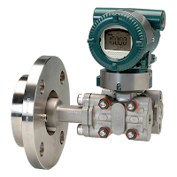
Hydrostatic level
Hydrostatic level instrument to tank
wall mounting (Yokogawa).
Hydrostatic pressure

A vertical column of fluid generates a pressure at the bottom of the column owing to the action of gravity on that fluid. The greater the vertical height of the fluid, the greater the pressure, all other factors being equal. This principle allows us to infer the level (height) of liquid in a vessel by pressure measurement.

Displacement

Displacer level instruments exploit Archimedes’ Principle to detect liquid level by continuously measuring the weight of an object (called the displacer) immersed in the process liquid. As liquid level increases, the displacer experiences a greater buoyant force, making it appear lighter to the sensing instrument, which interprets the loss of weight as an increase in level and transmits a proportional output signal.

Echo
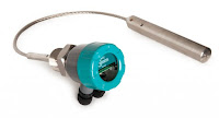
Radar level
Radar level transmitter (Hawk).
A completely different way of measuring liquid level in vessels is to bounce a traveling wave off the surface of the liquid – typically from a location at the top of the vessel – using the time-of-flight for the waves as an indicator of distance, and therefore an indicator of liquid height inside the vessel. Echo-based level instruments enjoy the distinct advantage of immunity to changes in liquid density, a factor crucial to the accurate calibration of hydrostatic and displacement level instruments. In this regard, they are quite comparable with float-based level measurement systems. Liquid-liquid interfaces may also be measured with some types of echo-based level instruments, most commonly guided-wave radar. The single most important factor to the accuracy of any echo-based level instrument is the speed at which the wave travels en route to the liquid surface and back. This wave propagation speed is as fundamental to the accuracy of an echo instrument as liquid density is to the accuracy of a hydrostatic or displacer instrument.

Weight

Weight level
Level can be determined by
weight using load cells (BLH).
Weight-based level instruments sense process level in a vessel by directly measuring the weight of the vessel. If the vessel’s empty weight (tare weight) is known, process weight becomes a simple calculation of total weight minus tare weight. Obviously, weight-based level sensors can measure both liquid and solid materials, and they have the benefit of providing inherently linear mass storage measurement. Load cells (strain gauges bonded to a steel element of precisely known modulus) are typically the primary sensing element of choice for detecting vessel weight. As the vessel’s weight changes, the load cells compress or relax on a microscopic scale, causing the strain gauges inside to change resistance. These small changes in electrical resistance become a direct indication of vessel weight.

Capacitive

Capacitive level instruments measure electrical capacitance of a conductive rod inserted vertically into a process vessel. As process level increases, capacitance increases between the rod and the vessel walls, causing the instrument to output a greater signal. Capacitive level probes come in two basic varieties: one for conductive liquids and one for non- conductive liquids. If the liquid in the vessel is conductive, it cannot be used as the dielectric (insulating) medium of a capacitor. Consequently, capacitive level probes designed for conductive liquids are coated with plastic or some other dielectric substance, so the metal probe forms one plate of the capacitor and the conductive liquid forms the other.

Radiation

Certain types of nuclear radiation easily penetrates the walls of industrial vessels, but is attenuated by traveling through the bulk of material stored within those vessels. By placing a radioactive source on one side of the vessel and measuring the radiation reaching the other side of the vessel, an approximate indication of level within that vessel may be obtained. Other types of radiation are scattered by process material in vessels, which means the level of process material may be sensed by sending radiation into the vessel through one wall and measuring back-scattered radiation returning through the same wall.

Power Specialties Sales Engineers are experts in industrial level control. Feel free to contact them at (816) 353-6550, or by visiting http://www.powerspecialties.com, for any level application.  They'll assure you get the best continuous level control for the application.

Content above abstracted from “Lessons In Industrial Instrumentation”
by Tony R. Kupholdt under the terms and conditions of the
Creative Commons Attribution 4.0 International Public License.

How Biofuels Are Produced

From biomass to biofuels
Biomass resources run the gamut from corn kernels to corn stalks, from soybean and canola oils to animal fats, from prairie grasses to hardwoods, and even include algae.

In the long run, we will need diverse technologies to make use of these different energy sources. Some technologies are already developed; others will be. Today, the most common technologies involve biochemical, chemical, and thermochemical conversion processes.

Ethanol, today’s largest volume biofuel, is produced through a biochemical conversion process. In this process, yeasts ferment sugar from starch and sugar crops into ethanol. Most of today’s ethanol is produced from cornstarch or sugarcane. But biochemical conversion techniques can also make use of more abundant “cellulosic” biomass sources such as grasses, trees, and agricultural residues.

Researchers develop processes that use heat, pressure, chemicals, and enzymes to unlock the sugars in cellulosic biomass. The sugars are then fermented to ethanol, typically by using genetically engineered micro- organisms. Cellulosic ethanol is the leading candidate for replacing a large portion of U.S. petroleum use.

A much simpler chemical process is used to produce biodiesel. Today’s biodiesel facilities start with vegetable oils, seed oils, or animal fats and react them with methanol or ethanol in the presence of a catalyst. In addition, genetic engineering work has produced algae with a high lipid content that can be used as another source of biodiesel.

Algae are a form of biomass which could substantially increase our nation’s ability to produce domestic biofuels. Algae and plants can serve as a natural source of oil, which conventional petroleum refineries can convert into jet fuel or diesel fuel—a product known as “green diesel.”

Researchers also explore and develop thermochemical processes for converting biomass to liquid fuels. One such process is pyrolysis, which decomposes biomass by heating it in the absence of air. This produces an oil-like liquid that can be burned like fuel oil or re ned into chemicals and fuels, such as “green gasoline.” Thermochemical processes can also be used to pretreat biomass for conversion to biofuels.

Another thermochemical process is gasification. In this process, heat and a limited amount of oxygen are used to convert biomass into a hot synthesis gas. This “syngas” can be combusted and used to produce electricity in a gas turbine or converted to hydrocarbons, alcohols, ethers, or chemical products. In this process, biomass gasifiers can work side by side with fossil fuel gasifiers for greater flexibility and lower net greenhouse gas emissions.

In the future, biomass-derived components such as carbohydrates, lignins, and triglycerides might also be converted to hydrocarbon fuels. Such fuels can be used in heavy-duty vehicles, jet engines, and other applications that need fuels with higher energy densities than those of ethanol or biodiesel.

Process Control Experts - Power Specialties, Inc.

Established in 1967, Power Specialties was founded on the concept that customer service is of primary importance. Our staff of Sales Engineers are well trained in the application and selection of instrumentation and control products. Specializing in providing instrumentation and control solutions for industry:
  • Ethanol / BioFuel
  • Agricultural and Specialty Chemical
  • Power
  • Pharmaceutical
  • Manufacturing
  • Oil and Gas Production

Visit http://www.powerspecialties.com or call (816) 353-6550.

Magnetic Flowmeters: Principles and Applications

Magnetic flowmeter
Magnetic flowmeter (Yokogawa)
Crucial aspects of process control include the ability to accurately determine qualities and quantities of materials. In terms of appraising and working with fluids (such as liquids, steam, and gases) the flowmeter is a staple tool, with the simple goal of expressing the delivery of a subject fluid in a quantified manner. Measurement of media flow velocity can be used, along with other conditions, to determine volumetric or mass flow. The magnetic flowmeter, also called a magmeter, is one of several technologies used to measure fluid flow.

In general, magnetic flowmeters are sturdy, reliable devices able to withstand hazardous environments while returning precise measurements to operators of a wide variety of processes. The magnetic flowmeter has no moving parts. The operational principle of the device is powered by Faraday's Law, a fundamental scientific understanding which states that a voltage will be induced across any conductor moving at a right angle through a magnetic field, with the voltage being proportional to the velocity of the conductor. The principle allows for an inherently hard-to-measure quality of a substance to be expressed via the magmeter. In a magmeter application, the meter produces the magnetic field referred to in Faraday's Law. The conductor is the fluid. The actual measurement of a magnetic flowmeter is the induced voltage corresponding to fluid velocity. This can be used to determine volumetric flow and mass flow when combined with other measurements.

The magnetic flowmeter technology is not impacted by temperature, pressure, or density of the subject fluid. It is however, necessary to fill the entire cross section of the pipe in order to derive useful volumetric flow measurements. Faradayís Law relies on conductivity, so the fluid being measured has to be electrically conductive. Many hydrocarbons are not sufficiently conductive for a flow measurement using this method, nor are gases.

Magmeters apply Faradayís law by using two charged magnetic coils; fluid passes through the magnetic field produced by the coils. A precise measurement of the voltage generated in the fluid will be proportional to fluid velocity. The relationship between voltage and flow is theoretically a linear expression, yet some outside factors may present barriers and complications in the interaction of the instrument with the subject fluid. These complications include a higher amount of voltage in the liquid being processed, and coupling issues between the signal circuit, power source, and/or connective leads of both an inductive and capacitive nature.

In addition to salient factors such as price, accuracy, ease of use, and the size-scale of the flowmeter in relation to the fluid system, there are multiple reasons why magmeters are the unit of choice for certain applications. They are resistant to corrosion, and can provide accurate measurement of dirty fluids ñ making them suitable for wastewater measurement. As mentioned, there are no moving parts in a magmeter, keeping maintenance to a minimum. Power requirements are also low. Instruments are available in a wide range of configurations, sizes, and construction materials to accommodate various process installation requirements.

As with all process measurement instruments, proper selection, configuration, and installation are the real keys to a successful project. Share your flow measurement challenges of all types with a process measurement specialist, combining your process knowledge with their product application expertise to develop an effective solution.

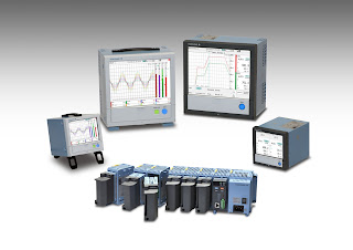
Yokogawa Smartdac+ Data Acquisition & Control for Paperless Recorders Type GX and GP

Yokogawa Smartdac+
Yokogawa Smartdac+ for GX/GP recorders
Recorders and data acquisition systems (data loggers) are used on production lines and at product development facilities in a variety of industries to acquire, display, and record data on temperature, voltage, current, flow rate, pressure, and other variables. Yokogawa offers a wide range of such products, and is one of the world’s top manufacturers of recorders. Since releasing the SMARTDAC+ data acquisition and control system in 2012, Yokogawa has continued to strengthen it by coming out with a variety of recorders and data acquisition devices that meet market needs and comply with industry-specific requirements and standards.

In 2017, Yokogawa introduced Release 4 of the SMARTDAC+® GX series panel-mount type paperless recorder, GP series portable paperless recorder, and GM series data acquisition system.

With this latest release, new modules are provided to expand the range of applications possible with SMARTDAC+ systems and improve user convenience. New functions include sampling intervals as short as 1 millisecond and the control and monitoring of up to 20 loops.

For more information, visit Power Specialties here, or call (816) 353-6550.

Fieldbus Equipped Process Control Instrumentation: Part Two of Two

FOUNDATION fieldbus
(Image courtesy of Lessons in Industrial Instrumentation
and Tony R. Kuphaldt and shared under Creative Commons
4.0 International Public License
).
Since automatic control decisions in FOUNDATION fieldbus are implemented and executed at the field instrument level, the reliance on digital signals (as opposed to analog) allows for a streamlined configuration of direct control system ports. If the central control device were to become overloaded for any reason, tasks related to control decisions could still be implemented by operators in the field. This decentralization of the system places less burden and emphasis on the overall central control unit, to the point where, theoretically, the central control unit could stop functioning and the instrumentation would continue performing process tasks thanks to the increased autonomy. Allowing for the instrumentation to function at such an increased level of operation provides a proverbial safety net for any system related issues, with the capacity for independent functionality serving as both a precaution and an example for how process technology continues to evolve from analog solutions to fully end to end digital instrumentation.

Even in terms of the FOUNDATION instrumentation itself, there were two levels of networks being developed at this increased level of operation, initially: the first, H1, was considered low speed, while H2 was considered high speed. As the design process unfolded, existing Ethernet technology was discovered to fulfill the needs of the high speed framework, meaning the H2 development was stopped since the existing technology would allow for the H1 network to perform to the desired standards. The physical layer of the H1 constitutes, typically, a two-wire twisted pair ungrounded network cable, a 100 ohm (typical) characteristic impedance, DC power being conveyed over the same two wires as digital data, at least a 31.25 kbps data rate, differential voltage signaling with a defined threshold for both maximum and minimum peak receive rates, and Manchester encoding. Optical fiber can be used on some installations in lieu of the twisted pair cable.

Most of these specifications were exactly designed to withstand extremely challenging process control environments while still not abandoning the philosophy of being easy to build and implement, especially in terms of new system establishment. The most crucial aspects of many process control systems are streamlined together, allowing for consistent communication and synchronization. All aspects are viewable from both the legacy central controller and also via each individual device. Despite the data rate of 31.25 kbps being relatively slow, what is sacrificed in terms of speed is more than made up for in terms of the system being compatible with imperfect cables and other hiccups which may destabilize a network with faster speeds. The evolved technology, ease of installation, and durability have made the H1 network a widely used implementation of the FOUNDATION fieldbus technology. Fieldbus is currently considered one of a few widely adopted industrial process control communications protocols.

Contact Power Specialties with any process instrumentation, or field device communication question you may have. Visit http://www.powerspecialties.com or call (816) 353-6550.

Fieldbus Equipped Process Control Instrumentation: Part One of Two

FOUNDATION Fieldbus
(Image courtesy of Lessons in Industrial Instrumentation
and Tony R. Kuphaldt and shared under Creative Commons
4.0 International Public License).
Autonomous control and digital instrumentation are two capabilities enabling highly precise or complex execution of process control functions. FOUNDATION fieldbus instrumentation elevates the level of control afforded to digital field instrumentation where, instead of only communicating with each other, instruments involved in particular process control systems can independently facilitate algorithms typically reserved for instruments solely dedicated to controlling other instruments. Fieldbus capable instrumentation has become the standard instrumentation for many process industry installations due to the fact the FOUNDATION design principle streamlines process systems. A large contributor to FOUNDATION's success has been faster installation as opposed to operational controllers which do not feature the fieldbus configuration. Newer process companies, or process control professionals seeking to establish a new system, have gravitated towards fieldbus due to the combined advantages of system conciseness and ease of implementation.

In a typical digital control system, dedicated controllers communicate with field instrumentation (the HART protocol is a prime example of digital communication at work in the industry). The host system controls configuration of instruments and serves as a central hub where all relevant control decisions are made from a single dedicated controller. Typically, these networks connect controllers and field devices through coupling devices and other "buses" which streamline many different instruments into a complete system.

FOUNDATION fieldbus approaches the same network scheme with an important difference. Whereas in a legacy or more conventional system, either algorithmic or manual decisions would need to be implemented via the dedicated system level controllers, instruments utilizing FOUNDATION fieldbus architecture can execute control algorithms at the local device level. The dedicated controller hub is still present, so that operators can view and monitor the entire network concurrently and make status changes. Algorithmic execution of control functions becomes entirely device reliant thanks to the FOUNDATION protocol. Additionally, even though FOUNDATION implements an advanced configuration, some operators use the capabilities introduced in the fieldbus upgrade to implement specific algorithms via each device while concurrently maintaining algorithms in the central controller. This dual algorithmic configuration allows for several advantages, including the ability for increased system precision.

Since individual devices in the control process are calibrated and able to execute their own control functions, issues in the process with particular devices can be isolated and dealt with in a more specified manner by technicians using the instruments in the field. The central operator retains the capacity to use the control hub to alter and direct the control system.

Stay tuned for Part Two.

Contact Power Specialties with any process instrumentation, or field device communication question you may have. Visit http://www.powerspecialties.com or call (816) 353-6550.