Showing posts with label BLH Nobel. Show all posts

Load Cells Used for Weighing Applications in Industrial Control

Load Cells Used for Weighing Applications

Physical science principles are integrated with technology and engineering to build devices critical to modern high speed, high accuracy system operation in industrial process monitoring and control. 

A load cell measures things ranging in size from very small to extremely large and is an essential component of weighing materials and equipment. Their usefulness applies to many process weighing applications across various industries.

In essence, a load cell is a force measurement device that acts as a transducer, transforming force into a unit of quantifiable electrical output in a predictable manner. While there are many different types of load cells, the strain gauge-based cell is the most used in many industries. These strain gauge cells typically have an accuracy range of 0.03 percent to 0.25 percent. Pneumatically based load cells are appropriate for circumstances demanding intrinsic safety and optimal hygiene. There are also hydraulic load cells that run without the requirement for a power supply for regions without a power grid.  These load cells operate on the same principle: a force acts on the cell, which then computes as a value. The value is processed to get an indicator of weight in engineering units. 

The deformation principle applies to strain gauge cells, where highly minute amounts of deformation, directly related to the stress or strain applied to the cell, are produced as an electrical signal with a value proportional to the load applied to the cell. The operating concept enables the creation of devices capable of providing accurate, precise measurements of a wide range of industrial products. 

Load cells' advantages include their endurance, accuracy, and flexibility to a wide range of applications, all of which contribute to their utility in a wide range of industries and applications. 

Learn more about load cells or process weighing applications from Power Specialties. Contact them at https://powerspecialties.com or (816) 353-6550 for more information.

BLH Tank Mount Series

BLH Tank Mount Series

BLH Nobel introduced its new Tank Mount Series of weighing equipment for process weighing applications.  The new series includes three different fully standardized weigh modules with off-the-shelf availability in capacities up to 200 tons and various suitable junction boxes and instruments.  It is an integrated solution for accurate and repeatable weighing of materials for multiple applications such as large silos, vessels, small ingredient storage bins, and clean-in-place batching processes.

Tank Mount Series Markets: 

  • Chemical
  • Food and Beverage
  • Pharmaceutical
  • Pulp and Paper

Known for its customizable, high-accuracy, smart weighing solutions, BLH Nobel is an established leader in process weighing.  The Tank Mount Series provides end-users as well as system integrators and OEMs a cost-competitive solution, consisting of two low and one high capacity range weigh modules with mV/V output:

With capacities up to 5 ton/tonnes, the metric TankMount weigh module and its imperial counterpart EconoMount weigh module are both well suited for general industrial applications that require retrofitting on existing structures or converting hoppers into a scale.  The weigh modules are rated IP 67 or better as a standard, with ATEX, FM, NEMA4, OIML, and NTEP, Class III, and IIIL certified versions available as an option.

With the KDH5 weigh module, the Tank Mount Series covers larger capacity needs up to 200 tons at accuracy levels of 0.075% of Rated Output.  Its compact and robust mechanical design features an integrated tilt guard for easy installation.  The weigh module is ideal for heavy silo weighing applications or weighbridges and offered as ATEX, IECEx, or FM approved versions at no additional cost.  Higher capacities and EN 1090 compliant versions are also available.

BLH Nobel offers various suitable junction boxes and instruments to provide complete weighing solutions in a one-stop-shop.  For example, the WIN5 weigh indicator is well suited for simple applications, which can benefit from its stainless steel enclosure, the high-contrast 6-digit LED display, and the operating pushbuttons are supporting tare weight zero settings of empty vessels.  The G5 DIN Rail Mount satisfies advanced process weighing and control instrument needs.  It is available as a DIN Rail version with an integrated display and functional keypad, easy navigation, and control directly at the production facility.  The G5 instrument family's modular hardware supports a wide variety of communication options via Ethernet, RS485, USB, Fieldbus, and analog output - for full flexibility.

Power Specialties, Inc.
https://powerspecialties.com
(816) 353-6550

Weight-based Level Control

Weight-based level instruments sense process level in a vessel by directly measuring the weight of the vessel. If the vessel’s empty weight (tare weight) is known, process weight becomes a simple calculation of total weight minus tare weight. Obviously, weight-based level sensors can measure both liquid and solid materials, and they have the benefit of providing inherently linear mass storage measurement. Load cells (strain gauges bonded to a steel element of precisely known modulus) are typically the primary sensing element of choice for detecting vessel weight. As the vessel’s weight changes, the load cells compress or relax on a microscopic scale, causing the strain gauges inside to change resistance. These small changes in electrical resistance become a direct indication of vessel weight.

The following photograph shows three bins used to store powdered milk, each one supported by pillars equipped with load cells near their bases:


When multiple load cells are used to measure the weight of a storage vessel, the signals from all load cell units must be added together (“summed”) to produce a signal representative of the vessel’s total weight. Simply measuring the weight at one suspension point is insufficient, because one can never be sure the vessel’s weight is distributed equally amongst all the supports.

Weight-based measurements are often employed where the true mass of a quantity must be ascertained, rather than the level. So long as the material’s density is a known constant, the relationship between weight and level for a vessel of constant cross-sectional area will be linear and predictable. Constant density is not always the case, especially for solid materials, and so weight-based inference of vessel level may be problematic.

In applications where batch mass is more important than height (level), weight-based measurement is often the preferred method for portioning batches. You will find weight-based portion measurements used frequently in the food processing industries (e.g. consistently filling bags and boxes with product), and also for custody transfer of certain materials (e.g. coal and metal ore).

One very important caveat for weight-based level instruments is to isolate the vessel from any external mechanical stresses generated by pipes or machinery. The following illustration shows a typical installation for a weight-based measurement system, where all pipes attaching to the vessel do so through flexible couplings, and the weight of the pipes themselves is borne by outside structures through pipe hangers:


Stress relief is very important because any forces acting upon the storage vessel will be interpreted by the load cells as more or less material stored in the vessel. The only way to ensure that the load cell’s measurement is a direct indication of material held inside the vessel is to ensure that no other forces act upon the vessel except the gravitational weight of the material.

A similar concern for weight-based batch measurement is vibration produced by machinery surrounding (or on) the vessel. Vibration is nothing more than oscillatory acceleration, and the acceleration of any mass produces a reaction force (F = ma). Any vessel suspended by weight-sensing elements such as load cells will induce oscillating forces on those load cells if shaken by vibration. This concern in particular makes it quite difficult to install and operate agitators or other rotating machinery on a weighed vessel.

An interesting problem associated with load cell measurement of vessel weight arises if there are ever electric currents traveling through the load cell(s). This is not a normal state of affairs, but it can happen if maintenance workers incorrectly attach arc welding equipment to the support structure of the vessel, or if certain electrical equipment mounted on the vessel such as lights or motors develop ground faults. The electronic amplifier circuits interpreting a load cell’s resistance will detect voltage drops created by such currents, interpreting them as changes in load cell resistance and therefore as changes in material level. Sufficiently large currents may even cause permanent damage to load cells, as is often the case when the currents in question are generated by arc welding equipment.

A variation on this theme is the so-called hydraulic load cell which is a piston-and-cylinder mechanism designed to translate vessel weight directly into hydraulic (liquid) pressure. A normal pressure transmitter then measures the pressure developed by the load cell and reports it as material weight stored in the vessel. Hydraulic load cells completely bypass the electrical problems associated with resistive load cells, but are more difficult to network for the calculation of total weight (using multiple cells to measure the weight of a large vessel).

Power Specialties can assist you with all of your process weighing requirements. Visit their website at https://powerspecialties.com or call (816) 353-6550.


Reprinted from "Lessons In Industrial Instrumentation" by Tony R. Kuphaldt – under the terms and conditions of the Creative Commons Attribution 4.0 International Public License.

Glossary of Technical Terms for Process Weighing

KIS Load Cell
KIS Load Cell (BLH Nobel)
BLH Nobel has been recognized as a leader in weighing technology, process weighing and force measurement. They design and deliver innovative, accurate industry-leading weighing and force measurement solutions and supply both standardized and custom systems and serve customers from a wide range of industries.

The following embedded document is an exhaustive compilation of technical terms used in process weighing, courtesy of BLH Nobel.

You can also download your own PDF version of the "Glossary of Technical Terms for Process Weighing" here.


Specializing in Providing Instrumentation and Control Solutions for Industry

Power Specialties provides a wide range of industrial control products, instrumentation, and equipment to a variety of industries including ethanol / biofuel, agricultural and specialty chemical, power, pharmaceutical, manufacturing, and oil and gas production. Products include; flow, level, pressure, temperature, analytical instrumentation, recorders, data acquisition, annunciators, loop controllers, steam jet vacuum systems, process weighing and instrument communications. Visit https://powerspecialties.com.

Power Specialties

Mounting Advice for the BLH Nobel KIS and KIM Load Cells

High-accuracy KIS and KIM load cells have several features that distinguish them from other load cells. They are easy to install and extremely accurate, even when subjected to dynamic process forces and severe environmental conditions. Due to their double cantilever design, they have a floating load point and are not affected by side forces up to 100%, making them excellent choices for applications subject to thermal expansion, vibrations and side force disturbances.


Introduction to Industrial Continuous Level Control

magnetic level gauge
Magnetic level
gauge combines
float technology
with level gauge
simplicity
(Hawk).
Many industrial processes require the accurate measurement of fluid or solid (powder, granule, etc.) height within a vessel. Some process vessels hold a stratified combination of fluids, naturally separated into different layers by virtue of differing densities, where the height of the interface point between liquid layers is of interest.

A wide variety of technologies exist to measure the level of substances in a vessel, each exploiting a different principle of physics. This chapter explores the major level-measurement technologies in current use.

Level gauges

Level gauges are perhaps the simplest indicating instrument for liquid level in a vessel. They are often found in industrial level-measurement applications, even when another level-measuring instrument is present, to serve as a direct indicator for an operator to monitor in case there is doubt about the accuracy of the other instrument.

Float

Perhaps the simplest form of solid or liquid level measurement is with a float: a device that rides on the surface of the fluid or solid within the storage vessel. The float itself must be of substantially lesser density than the substance of interest, and it must not corrode or otherwise react with the substance.
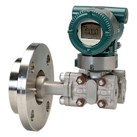
Hydrostatic level
Hydrostatic level instrument to tank
wall mounting (Yokogawa).
Hydrostatic pressure

A vertical column of fluid generates a pressure at the bottom of the column owing to the action of gravity on that fluid. The greater the vertical height of the fluid, the greater the pressure, all other factors being equal. This principle allows us to infer the level (height) of liquid in a vessel by pressure measurement.

Displacement

Displacer level instruments exploit Archimedes’ Principle to detect liquid level by continuously measuring the weight of an object (called the displacer) immersed in the process liquid. As liquid level increases, the displacer experiences a greater buoyant force, making it appear lighter to the sensing instrument, which interprets the loss of weight as an increase in level and transmits a proportional output signal.

Echo
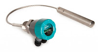
Radar level
Radar level transmitter (Hawk).
A completely different way of measuring liquid level in vessels is to bounce a traveling wave off the surface of the liquid – typically from a location at the top of the vessel – using the time-of-flight for the waves as an indicator of distance, and therefore an indicator of liquid height inside the vessel. Echo-based level instruments enjoy the distinct advantage of immunity to changes in liquid density, a factor crucial to the accurate calibration of hydrostatic and displacement level instruments. In this regard, they are quite comparable with float-based level measurement systems. Liquid-liquid interfaces may also be measured with some types of echo-based level instruments, most commonly guided-wave radar. The single most important factor to the accuracy of any echo-based level instrument is the speed at which the wave travels en route to the liquid surface and back. This wave propagation speed is as fundamental to the accuracy of an echo instrument as liquid density is to the accuracy of a hydrostatic or displacer instrument.

Weight

Weight level
Level can be determined by
weight using load cells (BLH).
Weight-based level instruments sense process level in a vessel by directly measuring the weight of the vessel. If the vessel’s empty weight (tare weight) is known, process weight becomes a simple calculation of total weight minus tare weight. Obviously, weight-based level sensors can measure both liquid and solid materials, and they have the benefit of providing inherently linear mass storage measurement. Load cells (strain gauges bonded to a steel element of precisely known modulus) are typically the primary sensing element of choice for detecting vessel weight. As the vessel’s weight changes, the load cells compress or relax on a microscopic scale, causing the strain gauges inside to change resistance. These small changes in electrical resistance become a direct indication of vessel weight.

Capacitive

Capacitive level instruments measure electrical capacitance of a conductive rod inserted vertically into a process vessel. As process level increases, capacitance increases between the rod and the vessel walls, causing the instrument to output a greater signal. Capacitive level probes come in two basic varieties: one for conductive liquids and one for non- conductive liquids. If the liquid in the vessel is conductive, it cannot be used as the dielectric (insulating) medium of a capacitor. Consequently, capacitive level probes designed for conductive liquids are coated with plastic or some other dielectric substance, so the metal probe forms one plate of the capacitor and the conductive liquid forms the other.

Radiation

Certain types of nuclear radiation easily penetrates the walls of industrial vessels, but is attenuated by traveling through the bulk of material stored within those vessels. By placing a radioactive source on one side of the vessel and measuring the radiation reaching the other side of the vessel, an approximate indication of level within that vessel may be obtained. Other types of radiation are scattered by process material in vessels, which means the level of process material may be sensed by sending radiation into the vessel through one wall and measuring back-scattered radiation returning through the same wall.

Power Specialties Sales Engineers are experts in industrial level control. Feel free to contact them at (816) 353-6550, or by visiting http://www.powerspecialties.com, for any level application.  They'll assure you get the best continuous level control for the application.

Content above abstracted from “Lessons In Industrial Instrumentation”
by Tony R. Kupholdt under the terms and conditions of the
Creative Commons Attribution 4.0 International Public License.

Process Weighing Controller: The BLH G5 Tech Manual

G5 Instruments
BLH Nobel G5 Instrument (panel mount)

The G5 Instruments are high performance single-channel weight indicators (PM model, panel mounted) or weight transmitters (RM model, DIN rail mounted) intended for industrial systems.

The basic function is to convert the signals from strain gauge transducers to useful weight information. Transducer excitation is included as well as parameter controlled signal processing, indication of output levels, error supervision and operation of optional external equipment.

As long as the error supervision detects no error, a signal called ‘In process’ is then present but if an error is detected, ‘In process’ will be off and a specific error message will be displayed. ‘In process’ can be set to control any digital output. Note that there are weighing channel specific and instrument specific error detection.

All functions in the G5 Instrument are controlled by set-up parameters. Setting of parameter values can be done from the PM front panel. Set-up of a RM model must be done with a web browser in a PC that is connected to the instrument via Ethernet. Maintenance functions can be accessed locally (PM) or remotely (PM and RM).

View the complete Technical Manual below, or download the G5 Tech Manual from here.

Measuring Exact Resultant Forces In Web Tension

Accuracy and consistency of web tension
Accuracy and consistency of web tension is critical.
Paper quality is determined by several factors including density and wrinkling. Problems in these areas are common in the paper industry. Uneven density and wrinkling of paper reels occurs if there is inadequate control over the positions and forces that control critical stages of the winding process, i.e. winding and spool transfer from the primary arm to the secondary arm. Because paper is sold by the ton not by the foot, the density is obviously extremely important. Wrinkling causes big problems in newspaper manufacture as paper breaks lead to stoppage of the printing presses.

One typical problem occurs when the nip force is controlled by measuring the pressures in the cylinders. Because the cylinders are mounted some distance away from the spool, where the nip force is actually generated, the friction that arises in the machine reduces the accuracy of the measurement results. As the mechanical components in cylinders become worn, this problem grows and the inaccuracy of measurements increases. If you do not have force control on both sides, and do not have control over the prevailing conditions for each reel, the nip forces will lack repeatability. This increases the risk of varying density and wrinkle formation, both when changing reels, and during winding where paper breaks may also occur. When lowering the spool from the primary arm to the secondary arm, changes may occur in the lowering speed, and misalignment between the reels may also result in varying density, wrinkles, and paper breaks.
 
Accuracy and consistency of web tension
One solution from BLH Nobel is based on mounting load cells directly at the point of force application, as well as on the position sensors in each cylinder. The load cells are therefore installed in the primary arm and secondary arm, and in the spool clamp. This allows us to measure values in real time, which means that we know the actual forces in the critical transfer from the primary to the secondary arm. Acceleration speed and force can then be adjusted by positioning cylinders that are controlled by means of software.

By adopting load cells, paper reels of the right density, with wrinkle free paper, and less paper breaks are the outcome. In a typical mill with 3 to 4 percent of the jumbo role being rejected due to wrinkling, using load cells reduced the waste to less than 0.5 percent.
For more information, visit Power Specialties at http://www.powerspecialties.com or call (816) 353-6550.