Power Specialties: Trust, Experience, Knowledge

In today’s industrial marketplace, it’s all about trust. Power Specialties earns your trust every day. From providing strong technical sales professionals who get your project done on time and on budget, to offering a select group of the most trusted and respected names in process control, Power Specialties continuously exceeds customer expectations.

https://powerspecialties.com
(816) 353-6550

Specializing in Providing Instrumentation and Control Solutions for Industry

Power Specialties provides a wide range of industrial control products, instrumentation, and equipment to a variety of industries including ethanol / biofuel, agricultural and specialty chemical, power, pharmaceutical, manufacturing, and oil and gas production. Products include; flow, level, pressure, temperature, analytical instrumentation, recorders, data acquisition, annunciators, loop controllers, steam jet vacuum systems, process weighing and instrument communications. Visit https://powerspecialties.com.

Power Specialties

pH/ORP Measurement for Reverse Osmosis

Reprinted from Yokogawa Application Note AN10B01B20-06E Rev2.

Industry: Refining, Food & Beverage, Power, Oil and Gas, Pulp and Paper, Chemical, Water
Products: pH/ORP and Conductivity Process Liquid Analyzers

Background Information
Osmosis
Click for larger view.
Processes requiring pure water must continually replace the water being consumed. Sources of replacement water are usually local supplies from a river or lake and therefore require pre-treatment and purification before it can be used in the process.

After preliminary purification which may include filtration, clarification and softening, further downstream, a two-pass reverse osmosis system and demineralization operations are typically employed to further purify the water.

Osmosis is the natural tendency of a fluid, usually water, to pass through a semipermeable membrane from a less concentrated solution into a more concentrated one, thus equalizing the concentrations on each side of the membrane.

In reverse osmosis (RO), pressure must be exerted on the side with the concentrated solution to force the water molecules across the semi-permeable membrane to the fresh (pure) water side.

This semi-permeable membrane inhibits the majority of dissolved impurities from passing through to the pure water side. The amount of impurities carried over depends on the type and condition of the membrane (i.e. age, cleanliness) and the amount of pressure applied (energy) to the process.

Not all the feed water passes through the membrane. Some is diverted to flow over them to cleanse away the rejected impurities in a cross-flow filtration mode.

The RO system produces one purified water stream called permeateand a second stream called concentrate, brine, or reject. Feedwaterenters the machine at fairly low pressure and flows through pre-filters to remove suspended particles, such as silt. Pre-filters are typically a replaceable cartridge type which provides a cost effective method for keeping the membrane clean. Typical life expectancy for these membranes is approximately three years.

RO systems are designed for automatic operation and require routine preventative and corrective maintenance. Common problems include membrane fouling and the use of improper flow rates. The result is reduced throughput capacity and shortened runs.

Membranes can fail altogether, resulting in excessive demand on downstream purification systems and poor quality product water.

Both pH and conductivity measurements are used to safeguard the successful operation of an RO system.

Some types of RO membranes are sensitive to feed water pH and can become damaged if the pH is outside the recommended range of 5 to 8 pH.A pH sensor upstream of the membrane can provide a feedback signal to control dosing of acidic or basic reagent to maintain the pH within acceptable limits.

Conductivity measurements are used at both the inlet and outlet of the RO unit to determine whether the total dissolved solids are being filtered effectively.

General Applications
Reverse osmosis systems can remove up to 100% of suspended solids and approximately 90% of dissolved solids, dissolved silica, alkalinity and hardness.

A common use for RO is for purifying water, removing salts and other impurities to improve the color, taste and other properties. It is regularly used for commercial and residential water filtration and is also one of the methods used for desalinization of seawater.

RO systems are capable of rejecting bacteria, salts, sugars, proteins, particles, dyes, and other constituents which have a molecular weight of greater than 150-250 Daltons.

The separation of ions with reverse osmosis is aided by charged particles. This means any dissolved ions which carry a charge, such as salts, are more likely to be rejected by the membrane than those that are not charged, such as organics. The larger the charge and the larger the particle, the more likely it will be rejected.

The majority of RO membranes are negatively charged when they are operated within the pH levels most commonly encountered in water applications.

Pure Water Applications
A two-pass RO system is typically installed upstream of the demineralizer. Its performance is pH dependent with the second-pass section most dramatically affected. While these changes are not significant in the majority of applications, variations become crucial to the success of high-purity water processing.

In addition, the effect of minor feedwaterconstituents, such as alkalinity and ammonia also play a role in achieving high-purity permeate.
The overall efficiencyof dissolved solids removal is usually determined utilizing a pair of conductivity measurements, one at the inlet (cell 1) and one at the outlet (cell 2). This is referred to as % rejection and calculated by the formula:

% rejection = [1-(cell2)/(cell 1)] x 100

For example if the inlet water had 200 ppm of dissolved solids and the outlet water had 10 ppm, the efficiency would be 95% rejection rate. A typical range for this type of application is 80% -100% rejection.

A final conductivity measurement after the 2nd stage is often used to determine the absolute quality of the outlet water.

Ammonia also affects the production of high purity water and may be present due to municipal chlorination of feed water or from organic contamination.

Ammonia (NH3) will through the membrane system in either the molecular or ionic (NH4+) form.
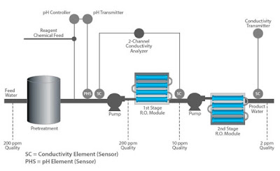
pH/ORP Measurement for Reverse Osmosis
Click for larger view.


Ammonium hydroxide is less conductive than ammonium carbonate [(NH4)2CO3] so it is not uncommon to find off-line samples or storage tank water with conductivity higher than that of on-line readings.

The pH values will be lower. This shift in pH is due to absorption of CO2from the air and the formation of carbonic acid in the water. Without the presence of ammonia, this type of contamination of high-purity water with CO2 would generate higher conductivity as well as the reduced pH.

For more information on pH/ORP Measurement for Reverse Osmosis contact Power Specialties by calling (816) 353-6550 or by visiting https://powerspecialties.com.

Swan DIST Water System Distribution Quality Monitors

Swan DISTSWAN Analytical Instrument introduced it's DIST Series Distribution Quality Monitor. The new line offers three options for measuring chlorine, pH, conductivity and turbidity on an easy to install and easy to maintain panel. Versatile output options are available to ensure water quality throughout your distribution system.

Three models are available for continuous monitoring of critical parameters for early warning at wells, pump stations and throughout the distribution system.

  • SWAN Dist 1 features reagentless free chlorine measurement. 
  • SWAN Dist 2 provides colorimetric, DPD based free chlorine measurement.
  • SWAN Dist 3 provides colorimetric, DPD based free and total chlorine measurement.

All three include pH and conductivity sensors in an easily accessible and easy to service flow cell. They also feature SWAN's non-contact Turbiwell turbidity monitoring.

Complete system comes pre-mounted on panel, ready for operation. Simple 4-20 outputs for each parameter used with SCADA provide an in depth record of water quality. Built in surveillance functions generate alarms if measurement is not valid, such as missing flow, empty reagents, valve and photometer functionality.

For more information, call Power Specialties at (816) 353-6550 or visit https://powerspecialties.com.


A Simple and Effective Understanding of Laminar Flow and Turbulent Flow

Laminar Flow and Turbulent Flow
Graphic courtesy of Wikimedia.org
Two very important terms to understand when studying flowing fluids are "turbulent flow" and "laminar flow".

Turbulent flow, caused by excessive kinetic energy in parts of a fluid flow, undergoes mixing and lateral irregularities characterized by eddies, recirculation, and apparent randomness. Fluid speed magnitude and direction changes chaotically in turbulent flow.

In contrast to turbulent flow, laminar flow occurs when a fluid flows in parallel "layers" with no interaction between the layers. When flowing at low velocities, fluids tend to flow without lateral (sideways) mixing, and adjacent layers glide past one another, analogous to playing cards sliding between others in a deck.

The video below provides a very simple, but very effective, demonstration of laminar and turbulent flow.

https://powerspecialties.com
(816) 353-6550


Wireless Technology in Industrial Automation

Yokogawa wireless transmitter
Yokogawa wireless
transmitter.

Reprinted with permission from Yokogawa.

The use of wireless technology in industrial automation systems offers a number of potential benefits, from the obvious cost reduction brought about by the elimination of wiring to the availability of better plant information, improved productivity and better asset management.

However, its practical implementation faces a number of challenges: not least the present lack of a universally agreed standard. This article looks at some of these challenges and presents the approach being taken by Yokogawa.

Introduction: The Wireless Landscape
In order to understand the ways in which wireless technology can aid the implementation of industrial automation systems, it is first important to clarify what is meant by the word ‘wireless’ in this context. Essentially, wireless can act at several levels within a plant:

  • RFID: At the simplest level, radio-frequency identification can aid asset inspection and tracking, safety and security, and location.
  • Wireless sensor networks: This is possibly the area where most attention is currently being focused, and embraces areas such as condition monitoring, wireless instruments and measurements.
  • Wireless LANs, covering areas such as mobile operator terminals, data logging, security, maintenance and IT. Wireless WANs, including long-distance broadband backhaul and high-bandwidth video applications.
When implemented within a typical plant, as depicted in the typical configuration shown in Fig.1, each of these areas can bring benefits as well as new opportunities. For example, the fact that plant and process information is available anywhere via wireless sensor networks leads to more and better quality information, with the benefits of distributed control and plant asset management spread throughout the plant.

wireless process control
Fig. 1 (click for larger view).
Another important benefit is improved workforce productivity. The fact that there are no wires leads to reduced installation and commissioning effort, while the fact that workers – whether operators or maintenance engineers – can be truly mobile eliminates the need for fixed local panels. Improved plant management results from the improved availability of video surveillance and people tracking for better safety and security, along with a reduced need to access hazardous or remote plant areas.

Wireless Sensor Networks
Of all the elements outlined above, wireless sensor networks are currently attracting the most attention, as most of the benefits directly relate to this area. Apart from the benefits of eliminating signal and power wiring, wireless sensor networks will open up measurement applications in sites that are hard to access, or where the wiring cost cannot be justified. They will also prove invaluable for the modernization of existing facilities, for temporary installations, or for locations where a power source is not available.

Wireless sensor networks also offer enhanced plant asset management through the freeing up of cable resources for higher-priority measurements in existing installations, the replacement of many traditional pressure gauges and temperature indicators, and the ability to make measurements that could not previously be justified. There is also a reduction in ‘blind spots’ through the ability to make measurements on rotating or moving equipment and in remote locations. A further important point is that, once established, wireless sensor networks are scalable: additional sensors can be added at low cost, and temporary measurements can be easily incorporated for process diagnostics and optimization.

Wireless Standards
In developing a universal standard for industrial automation wireless networks, a number of challenges emerge, not least because most license-free wireless networks use the same 2.4 GHz bandwidth, and many sensor networks are based on the IEEE 802.15.4 standard. Clearly there are concerns about coexistence and interference leading to reliability and latency problems and about multiple protocols sharing the same bandwidth.

Users have concerns about security, with the potential for jamming, sabotage and the compromising of network privacy. They also want systems that are open and backwards-compatible, interoperable and cost-effective to implement.

One thing is certain: the industry must strive to establish one global standard which covers communication from sensor to boardroom, which is designed with security in mind, and which is end-user driven. Unfortunately, this ideal scenario is unlikely to occur in the foreseeable future since two standards are currently being used by different industry players: WirelessHART and ISA100.11a. Although the two have some features in common, in reality they are very different. In particular, the scope of ISA100.11a is much wider, since – whereas WirelessHART focuses on monitoring from HART-enabled field instruments, ISA100.11a offers the scope to cover everything from field instruments to control- room integration. Moreover, it is compatible with a variety of protocols including FOUNDATION Fieldbus, Profibus, Modbus and others as well as HART, and allows over 1000 devices in a network compared to only around 250 with WirelessHART.

Yokogawa is committed to supporting ISA100.11a as part of the ISA100 family of standards as a preferred single international standard. In addition the ISA99 Security for Industrial Automation and Control Systems standard will be implemented to warrant overall security and privacy.

Wireless Strategy
Yokogawa is currently in the process of developing and evaluating a number of products for wireless sensor networks, with the emphasis on self-healing mesh network configurations, long battery life for field operation and a high degree of security. Field trials have been carried out to establish the characteristics of 2.4 GHz wireless transmission within typical environments such as refineries or chemical plants, from which a number of important lessons have been learned:
  • 2.4 GHz radio is sensitive to the presence of obstacles (pipework and other metal structures, for example). Wireless is not much affected by the local climate or by the presence of other wireless networks.
  • A mesh network configuration (involving more than two paths) is important for network reliability.
  • Response time is a useful indicator of the radio transmission conditions.
As a result of this experience, Yokogawa is pressing ahead with the development of wireless-based field instruments and access points as the initial stage of a ‘total solutions’ approach, and is implementing partnerships with other organizations to facilitate aspects such as the integration of auxiliary sensors as well as mobile worker networks, integration of surveillance camera systems and long-haul inter-plant connections.
wireless process control
Click for larger view.
A lesson learned from conducted wireless sensor field trials and real project implementations of mobile worker networks is that obstacles may affect the reliability, and hence the quality of service (QoS), of the network. Specifically, the proper location of access points and other devices and the possible need for inclusion of repeaters should be assessed beforehand. This is particularly critical for the successful operation of the mobile worker network, where roaming is essential.

It is expected that wireless sensor networks will gradually be adopted by the process industry. Although ISA100.11a is designed to accommodate control applications, initially the majority of applications will be for monitoring due to battery life limitations. In existing installations the benefits are obvious. Measurements for process monitoring and condition monitoring can be added where the existing infrastructure cannot accommodate them. State of the art greenfield sites are expected to be equipped with intelligent instruments that are mostly connected through wired instrumentation systems such as Foundation fieldbus while having several wireless networks for process and condition monitoring present.

Contact Power Specialties for Yokogawa wireless field devices and systems by calling (816) 353-6550 or by visiting https://powerspecialties.com.

RTD Sensors and Accessories for Clean-In-Place Applications

Pyromation CIP RTD
Pyromation CIP RTD
This one page publication features our CIP RTD Sensors and Accessories. Included are General Purpose CIP Sensors, Tank Sensors, Thermowells, and Transmitters.

Clean-In-Place units are provided with a Number 7 polished finish which exceeds 20 uin Ra. They meet or exceed finish requirements set forth by the 3A Sanitary Council Standard.

Download a PDF version of Clean-In-Place RTDS here, or read the embedded document below.

https://powerspecialties.com
(816) 353-6550