The Vibrating Fork Industrial Liquid Level Switch: Operation and Application

vibrating fork level switch
Vibrating Fork Level
Switch (Hawk)

When asked the primary reason to remember the year 1711, the event probably not on the minds of many is the invention of a device called the tuning fork. The tuning fork has been used as an source of resonating pitch for over three hundred years, and is still used to tune musical instruments today. While the tuning fork was initially applied to tune musical instruments, the concept of resonant frequency of a material or object has been utilized in numerous commercial, scientific, and industrial applications to provide feedback or insight into a process or operation. The vibrating fork level switch is one such industrial application where resonant frequency is used to deliver a data point or provide a control output for process operation.

The operating principle of the vibrating fork is based on the oscillating fork resonating at a known frequency in air when it is set in motion. Upon contacting a medium other than air, the resonant frequency is shifted, depending on the medium contacting or immersing the fork. Typically, fork-type level switches are installed on either the side or the top of a liquid process tank. An exciter keeps the fork oscillating, and a detector circuit monitors fork vibrating frequency, providing a change in the output signal when the frequency changes. Contact or immersion of the fork in liquid will change the fork vibrating frequency sufficiently to produce a change in output signal. Depending on the configuration of the level switch, it can function as a liquid level alarm, or provide a control output for a pump, valve, or other device. Sensor response, the change in fork vibration frequency, is a function of liquid density. Liquids with greater density will generally produce a larger frequency shift in the vibrating fork.
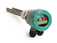
vibrating fork level switchThe wide use of vibrating level switches across various process industries is a testament to the reliability of the technology. The devices protect against overfill, indicate high and low points inside tanks, and are useful over a wide range of temperatures. A sturdy design, coupled with product variants that include a variety of sensor materials, selectable probe length, and specialized output features make vibrating fork switches applicable in many operations where level indication is needed. Chemical processing, mining, food and beverage, plastics, and other industries utilize the switches, thanks to their customizable designs and consistent performance. An advantage offered by vibrating fork level switches is a resistance to factors that sometimes confound other technologies employed for level indication. The devices will reliably function despite flow, bubbles, foam, vibration, and coating complexities related to the subject liquids. Additionally, vibrating fork switches are reliable in both high level and low level indication scenarios.

Highly viscous liquids are generally not good candidates for the application of a vibrating fork level switch. Some liquids present the potential for material accumulation between the forks, possibly resulting in poor performance. Both of these limitations are addressed by various design features incorporated by different manufacturers.

For more information, visit Power Specialties web site here or call (816) 353-6550.

Industrial Steam Boiler Optimization Toolkit

Steam generation
Steam generation
The primary function of a utility boiler is to convert water into steam to be used by a steam turbine/ generator in producing electricity. The boiler consists of a furnace, where air and fuel are combined and burned to produce combustion gases, and a feedwater tube system, the contents of which are heated by these gases. The tubes are connected to the steam drum, where the generated water vapor is drawn. In larger utility boilers, if superheated steam (low vapor saturation) is to be generated, the steam through the drum is passed through superheated tubes, which are also exposed to combustion gases. Boiler drum pressures can reach 2800 psi with temperatures over 680°F. Small to intermediate size boilers can reach drum pressures between 800 and 900 psi at temperatures of only 520°F if
superheated steam is desired. Small to intermediate size boilers are only being considered for this application note.

Bolier optimizationWith oil‐burning and gas‐burning boiler efficiencies over 90%, power plants are examining all associated processes and controls for efficiency improvements. Between 1 and 3% of the gross work produced by a boiler is used to pump feedwater. One method of improving overall efficiency is by controlling feedwater pump speed to save on pump power.


Read the entire optimization toolkit below (courtesy of Yokogawa).

New Power Specialties Company Video

Here is a new, short, introductory video about Power Specialties.

Celebrating our 50th year in business, Power Specialties was founded on the concept that customer service is of primary importance. Our staff of Sales Engineers are well trained in the application and selection of instrumentation and control products. Specializing in providing instrumentation and control solutions for industry:
  • Ethanol / BioFuel 
  • Agricultural and Specialty Chemical 
  • Power 
  • Pharmaceutical 
  • Manufacturing 
  • Oil and Gas Production

Basics of Load Cells Used in Process Weighing

BLH KIS Load Cell
Load cell with many industrial uses
including the weighing of hoppers,
mixing/blending tanks, and conveyors.
(Courtesy of BLH Nobel)   
In industrial application of process measurement and control, principles of the physical sciences are combined with technology and engineering to create devices essential to modern high speed, high accuracy system operation.

Load cells are the key components applied to weighing materials in modern processing. Load cells are utilized throughout many industries in process weighing operations. In application, a load cell can be adapted for measurement of items from the very small to the very large.

In essence, a load cell is a measurement tool which functions as a transducer, predictably converting force into a unit of measurable electrical output. While many types of load cells are available, the most popular cell in multiple industries is a strain gauge based cell. These strain gauge cells typically function with an accuracy range between 0.03% and 0.25%. Pneumatically based load cells are ideal for situations requiring intrinsic safety and optimal hygiene and, for locations without a power grid, there are even hydraulic load cells, which function without need for a power supply. These different types of load cells follow the same principle of operation: a force acts upon the cell (typically the weight of material or an object) which is then returned as a value. Processing the value yields an indication of weight in engineering units. For strain gauge cells, the principle of deformation applies, where extremely small amounts of deformation, directly related to the stress or strain being applied to the cell, are output as an electrical signal with value proportional to the load applied to the cell. The operating principle allows for development of devices delivering accurate, precise measurements of a wide range of industrial products. Advantages of load cells include their longevity, accuracy, and adaptability to many applications, all of which contribute to their usefulness in so many industries and applications.

For more information on any process weighing application, visit Power Specialties at http://www.powerspecialties.com or call (816) 353-6550.

Showing the Difference in Function Between High and Low Pressure Ports on a Differential Pressure Transmitter

The following video demonstrates the different responses of a differential pressure transmitter to both positive and negative pressures applied to its high and low pressure ports. The response of pressure and vacuum to the "high" port is opposite the effect of pressure and vacuum (respectively) applied to the "low" port.

Industrial Temperature Sensors and Indicators

Variety of electrical temperature sensors
Variety of electrical temperature sensors (Pyromation)
Temperature sensors are vital to everyday products and in the manufacturing of just about every product we use. Household ovens, refrigerators, and air conditioners all depend on temperature control to function properly and temperature control is essential in all process industries such as chemical, power, refinery, food processing, telecom, cement, fertilizer, pull & paper, plastics and petro-chemical.

Temperature sensors are devices which are used to temperature measurement of a medium (i.e. liquid, solid or gas). The sensor detects change in the temperature, and accordingly, change its physical or electrical property in a manner that can be measured. These sensors come in many different forms and are used for a wide variety of applications.

We as human’s simply sense temperature as hot or cold, but in process control, precise measurement of temperature is required in order to control a process efficiently. Accordingly, the correct temperature sensing device needs to be properly selected.

Types of Temperature Sensors

vapor actuated temperature indicator
Vapor actuated temperature indicator (REOTEMP)
Mechanical temperature sensors and indicators:

Devices that use the physical expansion and contraction of materials (like non-compressable fluids,
vapors, or differential metals) to mechanically open or close a set of contacts.

  • Examples of mechanical temperature sensors are bulb and capillary thermostats, thermometers, mechanical temperature switches, and bi-metallic thermostats.
Electrical temperature sensors:

These sensors undergo a measurable electrical change such as resistance, voltage, or current proportional to a given change in temperature.
Temperature Probe Assembly

  • Examples are thermocouples which generate a micro-voltage based upon a temperature differential between two dissimilar metals; RTDs that increase resistance as the sensing temperature increases; and thermistors,  which dramatically decrease resistance as temperature increases. 
Electrical temperature sensors can be housed in a wide variety of sheaths and/or wells for protection, and come in varying tolerances and accuracies to best suit their intended use.

For more information on temperature sensors, contact Power Specialties at (816) 353-6550 or visit http://www.powerspecialties.com.

Basics of Rotameters (Variable Area Flowmeters)

Rotameter by Yokogawa
Rotameter (Yokogawa)
A rotameter is a flow measuring device that belongs to a group of instruments called variable area flowmeters. For decades variable area flowmeters have become established in industrial measurement technology with an economical, mature measurement principle.

The variable area flowmeter is an instrument for metering the flowrate of liquids and gases in a pipeline. It includes a vertically oriented conical tube, whose diameter is larger at the top than at the bottom, through which the fluid flows upward and in which a vertically moving float is positioned. The height of the float in the tube increases as the flowrate increases in such a manner that the resistance to the flow is always balanced by the weight of the float and remains constant regardless of the flowrate. The height of the float in the tube is a measure of the flowrate.

The value of the flowrate can be read from a scale. Variable area flowmeters are the most cost effective solution for almost all applications involving the measurement of industrial process liquids, gases or steam. They meet the application requirements by featuring a wide range of design varieties and sizes.

Rotameters offer long life and high reproducibility and are excellent mechanical back-up meters because no external power supply is needed. For more information on rotameters (variable area flowmeters) visit http://www.powerspecialties.com or call Power Specialties at (816) 353-6550.

The video below does a great job introducing the various types and uses for rotameters.