PID Control Tutorial

 YS1700 Programmable Indicating Controller
PID is an acronym for proportional band, integral and derivative. This control action allows a measurement (process variable) to be controlled at a desired set point by continuously adjusting a control output. These control parameters act on the error or deviation between set point and process variable.

P: Proportional Band in %
I: Integral Time in sec/repeat
D: Derivative Time in seconds


Proportional Control

PID Control TutorialWith proportional band, the controller output changes in "proportion" to the error between process variable and set point. The amplitude of the change is adjustable from 1% to 999.9%.


Proportional Control


Refer to Figure 1. This example of a temperature controller shows a proportional band setting of 5%.

  • Set point = 500°
  • Measurement range = 0-1000°
  • 5% PB = 5% of 1000° = 50°
  • 100% output at 475° (2.5% of 1000°)
  • 0% output at 525° (2.5% of 1000°)

If the process variable equals the set point (500°), there is a 50% output. As the temperature decreases, the proportional band increases the output linearly toward 100% as the temperature falls toward 475°. The output decreases below 50% as the temperature rises toward 525°.

In this example, a small change in temperature provides a large change in output. If the setting is too small for the process dynamics, oscillations will occur and will not settle at set point. A large PB setting makes the controller act sluggish and will not respond adequately to upsets. Since proportional control does not incorporate the time that the error has existed, there will always be an offset from set point.

Typically, flow or pressure controllers have a much larger proportional setting due to a possible narrower measurement range and fast process reaction to a change in the control output. For example, a flow controller may have an input range of 0 to 60gpm and a set point of 30gpm.

  • Measurement range = 60gpm
  • Set point = 30gpm
  • 100% PB = 100% of 60 = 60gpm
  • 100% output at 0gpm
  • 0% output at 60gpm

Proportional + Manual Reset

PID Control TutorialTo eliminate the inherent offset observed with proportional control, a manual reset function can be used. Virtually no process requires precisely 50% output to maintain the process variable at the set point. An offset will be present. Manual reset allows the user to bias the output accordingly to compensate for the steady state offset using P only. Refer to Figure 2.

Proportional + Automatic Reset (Integral)

PID Control TutorialAutomatic reset or integral action corrects for any offset between set point and process variable
automatically by shifting the proportional band over a pre-defined time. The integral time repeats the proportional action over the time set. Integral redefines the output requirements at the set point until the process variable and set point are equal. Integral engineering units vary by controller manufacturer. Some use repeats/minute (reset rate), minutes/repeat or seconds/repeat. In Figure 3, seconds/repeat is used. The integral term is added as follows:

Proportional + Automatic Reset (Integral)
The smaller the integral number, the proportional action will be repeated more often. If integral is too small, the process variable will oscillate through set point and create erratic control action. If the number is too large, the action will be sluggish and unable to compensate for process upsets.

The integral number should be approximately 5 times the dead/lag time of the process variable. If the output is manually changed, dead time is defined as the time required for the process variable to initially react after the change. The length of time that it takes for the process variable to stabilize at a steady state is lag time.

  • Example: 40 sec (dead/lag) x 5 = 200 sec/repeat

Proportional + Integral + Derivative

PID Control TutorialDerivative action is used primarily in processes with long dead and lag times. This control function looks at the rate of change of the error and adjusts the control output based on that rate. The derivative term is added to the control algorithm as follows:
Proportional + Integral + Derivative


The amount of derivative added to the control output is based in time units. Figure 4 shows how derivative acts on the proportional band. The dashed line shows a proportional only control due to a process variable error from set point.

Using derivative (solid line), the control output jumps up, rises in a ramp and then falls back to proportional control action when the error becomes constant. In essence, it applies the "brakes" on the process error by quickly shifting the proportional band. Derivative has no effect on the output if the error is not changing. The derivative term should be approximately ¼ the integral time.

Derivative is typically not used in control loops with short dead/lag time, e. g., flow or pressure. This is an anticipatory action that will contribute to the inherent instability of these fast acting control loops.

Reprinted with permission from Yokogawa Corp.

Manual Tank Level Transmitter Adjustment on Yokogawa DPharp Transmitters

Yokogawa DPharp
If you have ever replaced a level transmitter with remote seals on a tank, you know the problems you may face if the tank can't be empty to allow you to correct for an elevated or suppress zero. With today's smart transmitters, this is now an easy thing to do.

Watch the video below for a quick tutorial on spanning and zero'ing the level transmitter.

For more information about Yokogawa products in Kansas, Missouri, Iowa, and Nebraska, contact Power Specialties by visiting www.powerspecialties.com or calling (816) 353-6550.

Measuring Exact Resultant Forces In Web Tension

Accuracy and consistency of web tension
Accuracy and consistency of web tension is critical.
Paper quality is determined by several factors including density and wrinkling. Problems in these areas are common in the paper industry. Uneven density and wrinkling of paper reels occurs if there is inadequate control over the positions and forces that control critical stages of the winding process, i.e. winding and spool transfer from the primary arm to the secondary arm. Because paper is sold by the ton not by the foot, the density is obviously extremely important. Wrinkling causes big problems in newspaper manufacture as paper breaks lead to stoppage of the printing presses.

One typical problem occurs when the nip force is controlled by measuring the pressures in the cylinders. Because the cylinders are mounted some distance away from the spool, where the nip force is actually generated, the friction that arises in the machine reduces the accuracy of the measurement results. As the mechanical components in cylinders become worn, this problem grows and the inaccuracy of measurements increases. If you do not have force control on both sides, and do not have control over the prevailing conditions for each reel, the nip forces will lack repeatability. This increases the risk of varying density and wrinkle formation, both when changing reels, and during winding where paper breaks may also occur. When lowering the spool from the primary arm to the secondary arm, changes may occur in the lowering speed, and misalignment between the reels may also result in varying density, wrinkles, and paper breaks.
 
Accuracy and consistency of web tension
One solution from BLH Nobel is based on mounting load cells directly at the point of force application, as well as on the position sensors in each cylinder. The load cells are therefore installed in the primary arm and secondary arm, and in the spool clamp. This allows us to measure values in real time, which means that we know the actual forces in the critical transfer from the primary to the secondary arm. Acceleration speed and force can then be adjusted by positioning cylinders that are controlled by means of software.

By adopting load cells, paper reels of the right density, with wrinkle free paper, and less paper breaks are the outcome. In a typical mill with 3 to 4 percent of the jumbo role being rejected due to wrinkling, using load cells reduced the waste to less than 0.5 percent.
For more information, visit Power Specialties at http://www.powerspecialties.com or call (816) 353-6550.

Introduction to Industrial Transmitters: Transmitters 101

Differential Pressure Transmitter
(Yokogawa)
Transmitters are process control field devices. They receive input from a connected process sensor, then convert the sensor signal to an output signal using a transmission protocol. The output signal is passed to a monitoring, control, or decision device for use in documenting, regulating, or monitoring a process or operation.

In general, transmitters accomplish three steps, including converting the initial signal twice.

The first step is the initial conversion which alters the input signal to make it linear. After an amplification of the converted signal, the second conversion changes the signal into either a standard electrical or pneumatic output signal that can be utilized by receiving instruments and devices. The third and final step is the actual output of the electrical or pneumatic signal to utilization equipment  controllers, PLC, recorder, etc.

Transmitters are available for almost every measured parameter in process control, and often referred to according to the process condition which they measure. Some examples.
  • Pressure transmitters
  • Temperature transmitters
  • Flow transmitters
  • Level transmitters
  • Vibration transmitters
  • Current, voltage & power transmitters
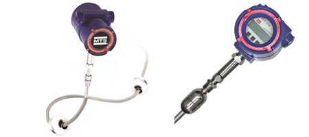
  • Level Transmitter
    Level Transmitter (MTS)
  • PH, conductivity, dissolved gas transmitters, etc. 
Output signals for transmitters, when electrical, often are either voltage (1-5 or 2-10 volts DC) or
current (4-20 mA). Power requirements can vary among products, but are often 110/220 VAC or 24 VDC.  Low power consumption by electrical transmitters can permit some units to be loop powered, operating from the voltage applied to the output current loop. These devices are also called two-wire transmitters because only two conductors are connected to the unit. Unlike the two wire system which only needs two wires to power the transmitter and analog signal output, the four-wire system requires four separate conductors, with one pair serving as the power supply to the unit and a separate pair providing the output signal path. Pneumatic transmitters, while still in use, are continuously being supplanted by electrical units that provide adequate levels of safety and functionality in environments previously only served by pneumatic units.

Temperature and Flow Transmitter
(Fox Thermal Instrument)
Many transmitters are provided with higher order functions in addition to merely converting an input signal to an output signal. On board displays, keypads, Bluetooth connectivity, and a host of industry standard communication protocols can also be had as an integral part of many process transmitters. Other functions that provide alarm or safety action are more frequently part of the transmitter package, as well.

Wireless transmitters are also available, with some operating from battery power and negating the need for any wired connection at all. Process transmitters have evolved from simple signal conversion devices to higher functioning, efficient, easy to apply and maintain instruments utilized for providing input to process control systems.

The Vibrating Fork Industrial Liquid Level Switch: Operation and Application

vibrating fork level switch
Vibrating Fork Level
Switch (Hawk)

When asked the primary reason to remember the year 1711, the event probably not on the minds of many is the invention of a device called the tuning fork. The tuning fork has been used as an source of resonating pitch for over three hundred years, and is still used to tune musical instruments today. While the tuning fork was initially applied to tune musical instruments, the concept of resonant frequency of a material or object has been utilized in numerous commercial, scientific, and industrial applications to provide feedback or insight into a process or operation. The vibrating fork level switch is one such industrial application where resonant frequency is used to deliver a data point or provide a control output for process operation.

The operating principle of the vibrating fork is based on the oscillating fork resonating at a known frequency in air when it is set in motion. Upon contacting a medium other than air, the resonant frequency is shifted, depending on the medium contacting or immersing the fork. Typically, fork-type level switches are installed on either the side or the top of a liquid process tank. An exciter keeps the fork oscillating, and a detector circuit monitors fork vibrating frequency, providing a change in the output signal when the frequency changes. Contact or immersion of the fork in liquid will change the fork vibrating frequency sufficiently to produce a change in output signal. Depending on the configuration of the level switch, it can function as a liquid level alarm, or provide a control output for a pump, valve, or other device. Sensor response, the change in fork vibration frequency, is a function of liquid density. Liquids with greater density will generally produce a larger frequency shift in the vibrating fork.

vibrating fork level switchThe wide use of vibrating level switches across various process industries is a testament to the reliability of the technology. The devices protect against overfill, indicate high and low points inside tanks, and are useful over a wide range of temperatures. A sturdy design, coupled with product variants that include a variety of sensor materials, selectable probe length, and specialized output features make vibrating fork switches applicable in many operations where level indication is needed. Chemical processing, mining, food and beverage, plastics, and other industries utilize the switches, thanks to their customizable designs and consistent performance. An advantage offered by vibrating fork level switches is a resistance to factors that sometimes confound other technologies employed for level indication. The devices will reliably function despite flow, bubbles, foam, vibration, and coating complexities related to the subject liquids. Additionally, vibrating fork switches are reliable in both high level and low level indication scenarios.

Highly viscous liquids are generally not good candidates for the application of a vibrating fork level switch. Some liquids present the potential for material accumulation between the forks, possibly resulting in poor performance. Both of these limitations are addressed by various design features incorporated by different manufacturers.

For more information, visit Power Specialties web site here or call (816) 353-6550.

Industrial Steam Boiler Optimization Toolkit

Steam generation
Steam generation
The primary function of a utility boiler is to convert water into steam to be used by a steam turbine/ generator in producing electricity. The boiler consists of a furnace, where air and fuel are combined and burned to produce combustion gases, and a feedwater tube system, the contents of which are heated by these gases. The tubes are connected to the steam drum, where the generated water vapor is drawn. In larger utility boilers, if superheated steam (low vapor saturation) is to be generated, the steam through the drum is passed through superheated tubes, which are also exposed to combustion gases. Boiler drum pressures can reach 2800 psi with temperatures over 680°F. Small to intermediate size boilers can reach drum pressures between 800 and 900 psi at temperatures of only 520°F if
superheated steam is desired. Small to intermediate size boilers are only being considered for this application note.

Bolier optimizationWith oil‐burning and gas‐burning boiler efficiencies over 90%, power plants are examining all associated processes and controls for efficiency improvements. Between 1 and 3% of the gross work produced by a boiler is used to pump feedwater. One method of improving overall efficiency is by controlling feedwater pump speed to save on pump power.


Read the entire optimization toolkit below (courtesy of Yokogawa).

New Power Specialties Company Video

Here is a new, short, introductory video about Power Specialties.

Celebrating our 50th year in business, Power Specialties was founded on the concept that customer service is of primary importance. Our staff of Sales Engineers are well trained in the application and selection of instrumentation and control products. Specializing in providing instrumentation and control solutions for industry:
  • Ethanol / BioFuel 
  • Agricultural and Specialty Chemical 
  • Power 
  • Pharmaceutical 
  • Manufacturing 
  • Oil and Gas Production